

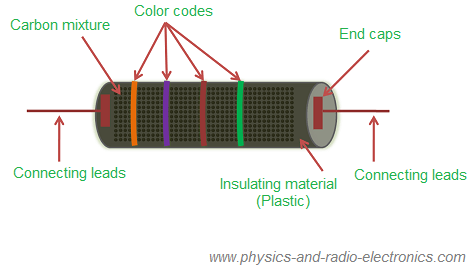


what is a resistor construction circuit diagram and. resistor resistors are employed in several electrical as well as electronic circuits to make a known voltage drop otherwise current to voltage c to v relationship when the flow of current in a circuit is identified then a resistor can be utilized for creating an identified potential difference which.
resistor wikipedia. a resistor is a passive two terminal electrical component that implements electrical resistance as a circuit element in electronic circuits resistors are used to reduce current flow adjust signal levels to divide voltages bias active elements and terminate transmission lines among other uses high power resistors that can dissipate many watts of electrical power as heat may be used as part of motor controls in power distribution systems or as test loads for generators fixed resistors have resistances that only change s. resistors ohm s law electronics textbook. a circuit diagram electrical diagram elementary diagram electronic schematic is a graphical representation of an electrical circuit a pictorial circuit diagram uses simple images of components while a schematic diagram shows the components and interconnections of the circuit using standardized symbolic representations the presentation of the interconnections between circuit. images of resistor electrical circuit diagram. resistor symbols of electrical electronic circuit diagram resistor potentiometer variable resistor table of resistor symbols resistor ieee resistor reduces the current flow resistor iec potentiometer ieee adjustable resistor has 3 terminals potentiometer iec. circuit diagram wikipedia. 107 rows electrical symbols electronic circuit symbols of schematic diagram resistor. resistor symbols circuit symbols. a circuit breaker in series before the parallel branches can prevent overloads by automatically opening the circuit a 15 a circuit operating at 120 v consumes 1 800 w of total power p vi 120 v 15 a 1 800 w total power in a parallel circuit is the sum of the power consumed on the individual branches.
electrical symbols electronic symbols schematic symbols. 03 10 2013 sometimes it can be hard to understand what the basic electronic components do earlier i have written about what an inductor do and what a capacitor do but what about the resistor the resistor is a component that resists current. resistors in circuits practice the physics hypertextbook. 09 12 2012 schematic diagrams symbols electrical circuits resistors capacitors inductors diodes drawing electric circuits with volt meters and ammeters duration 3 04. what is a resistor and what does it do build electronic. create an electrical engineering diagram basic electrical circuits and logic industrial control systems systems these templates open an unscaled drawing page in portrait orientation you can change these settings at any time drag electrical component. how to draw simple electric circuits lesson youtube. create an electrical engineering diagram visio.
resistor adalah,resistor ac,resistor adalah pdf,resistor array,resistor adalah jurnal,resistor ac mobil,resistor adalah komponen dasar elektronika,resistor and capacitor in parallel,resistor and capacitor in series,resistor and capacitor,electrical alternans,electrical appliances,electrical adalah,electrical avionic adalah,electrical autocad,electrical alternans ecg,electrical and electronics engineering,electrical and computer engineering,electrical activity of the heart,electrical accessories,circuit adalah,circuit analysis,cricut australia,cricut alternative,circuit app,circuit arcade bar,cricut air 2,circuit apartments,circuit analyzer,circuit abbreviation,diagram alir,diagram alir penelitian,diagram adalah,diagram activity,diagram alir adalah,diagram aktivitas,diagram alir proses produksi,diagram analisis swot,diagram alir data,diagram alir online
