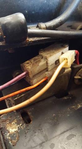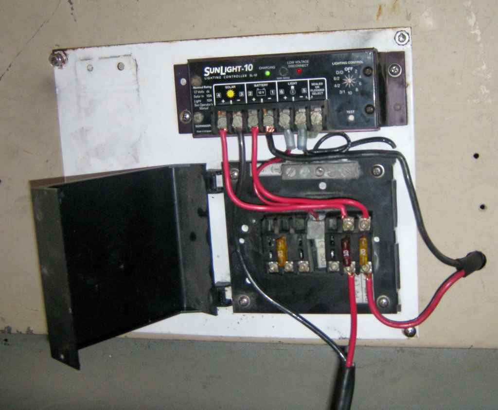


what is instrument hook up diagram instrument hook up. instrument hook up diagram is also called installation drawing specifies the scope of work between mechanical and instrumentation departments it is a detailed drawing showing typical installation of an instrument in a correct manner so that the instrument operates properly and prevent issues which could potentially affect the measurement such as liquid trap in gas impulse.
what is hook up drawing and how to read a hook up drawing. 13 01 2015 instrumentation and control engineering calibration procedures instrumentation electrical interview question instrumentation job opportunities piping instrument diagram symbols flow transmitter calibration dp type transmitter calibration control valve calibration flow measurement level measurement temperature measurement hook up diagram instrument data. solar panel wiring installation diagrams electrical tech. all about solar panel wiring installation diagrams step by step solar panel installation tutorials with batteries ups inverter and load calculation in your suggested scheme there are two power converters in the path from solar panels to the batteries whereas in the other model that you mentioned one power converter i e the. images of electrical hook up diagram. hook up diagram of audio video system is a detailed drawing showing the audio video connections in a correct manner so that system operates properly using the hook up diagram you can understand how the elements of your audio video system should be installed conceptdraw pro allows you to draw the hook up diagram of audio video system easily using the set of special libraries provided by audio. how to create a hook up diagram making your audio and. rewiring or wiring a trailer not sure about the wiring the 7 pin connections use this handy trailer wiring diagram for a quick reference for various electrical connections for trailers. trailer wiring diagram wiring diagrams for trailers. many diagram electrical wiring circuits still use this term don t worry some people can t let go of the past for us modern folk it s 120 volt circuits a 240 volt diagram electrical wiring circuit is just two 120 volt circuits put together for that extra bit of umph.
electrical wiring diagram. 16 03 2018 electric motor wiring diagram 220 to 110 building wiring representations reveal the approximate areas and also interconnections of receptacles illumination and also irreversible electrical solutions in a structure. electric motor wiring diagram 220 to 110 sample wiring. 14 06 2015 trailer wiring hook up diagram thinking out side box loading unsubscribe from thinking out side box how electric trailer brakes work duration 3 47 ghostses 465 610 views. trailer wiring hook up diagram youtube. 19 11 2013 hookup drawings 1 instrument installation hook up presented by a bagherian 2 contents title index list thermocouple installation arrangement at orifice plates orifice plates fabrication installaion of pressure piping hook up air piping hook up installation mounting hook up steam tracing installation of level instruments condensate pot instrumentation standard panels piping. hookup drawings slideshare. decide what level of provision the electrical hook up box must answer hook up boxes are available with single 30 amp and single 50 amp outlets and with multiple outlets featuring a 50 amp outlet served by a 50 amp breaker a 30 amp outlet served by a 30 amp breaker and a number of 20 amp outlets served by a 20 amp breakers. how to wire an rv electrical hook up box it still runs.